Digital Electronics
Contents
Introduction
Digital electronics is a way to visualize boolean algebra using drawn-out circuits (also known as logic gates). Be sure to make sure you understand all of the boolean operations; check out the Boolean Algebra page if needed. If you understand boolean algebra, you understand digital electronics.
Do note that there may be multiple ways to display the same boolean expression.
Definitions
Please refer to the table below. Operators that were not mentioned on the Boolean Algebra page will come with an extra explanation.
| Name | Logic Gate | Algebraic Expression | Extra Notes |
|---|---|---|---|
| BUFFER |  |
$X = A$ |
This logic gate doesn't really do much. The output is the input. |
| NOT |  |
$X = \overline{A} = \neg A$ |
|
| AND | 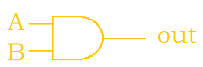 |
$X = AB = A \bullet B$ |
|
| NAND | 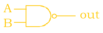 |
$X = \overline{AB} = \overline{A \bullet B}$ |
This is the opposite of the and operator. Whatever is evaluated as true for the and operator becomes false, and vice versa. |
| OR | 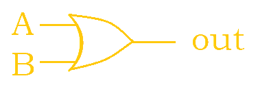 |
$X = A + B$ |
|
| NOR | 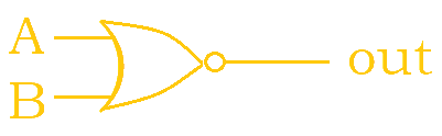 |
$X = \overline{A + B}$ |
This is the opposite of the or operator. Whatever is evaluated as true for the or operator becomes false, and vice versa. |
| XOR | 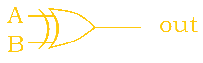 |
$X = A \oplus B$ |
|
| XNOR | 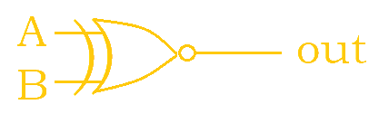 |
$X = \overline{A \oplus B} = A \odot B$ |
Notice how adding the little extra circle causes the logic gate to become negated. So, for example, OR becomes NOR after adding the little circle is added to the OR logic gate. Now, when it comes to reading the overall circuit, the most important thing is to keep track of what comes first. Reference the lines to know the order that the logic gates should be evaluated in; look from left to right.
Sample Problems
1. Write out the following circuit as a boolean expression. Then, simplify.
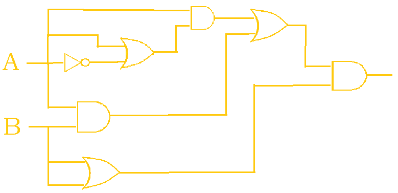
The following solution below breaks down the construction of the boolean expression into smaller steps. This process may not necessarily be the same one that you may have taken, but it is just one possible way to think about it.
$\overline{A}$$A + \overline{A}$$A \bullet (A + \overline{A})$$A \bullet (A + \overline{A}) , AB$-> A comma was used to separate two chunks of the expression that have not been merged yet.$(A \bullet (A + \overline{A})) + AB$-> The two chunks have now been merged.$(A \bullet (A + \overline{A})) + AB , (B + B)$$((A \bullet (A + \overline{A})) + AB) \bullet (B + B)$
Now, this expression has to be simplified; knowing the laws from the Boolean Algebra page is essential.
$((A \bullet (A + \overline{A})) + AB) \bullet (B + B)$$((A \bullet 1) + AB) \bullet (B + B)$$(A + AB) \bullet (B + B)$$A \bullet (B + B)$$A \bullet B$
Thus, our final answer is: $AB$.
2. How many ordered 3-tuples (A, B, C) make the following circuit TRUE?
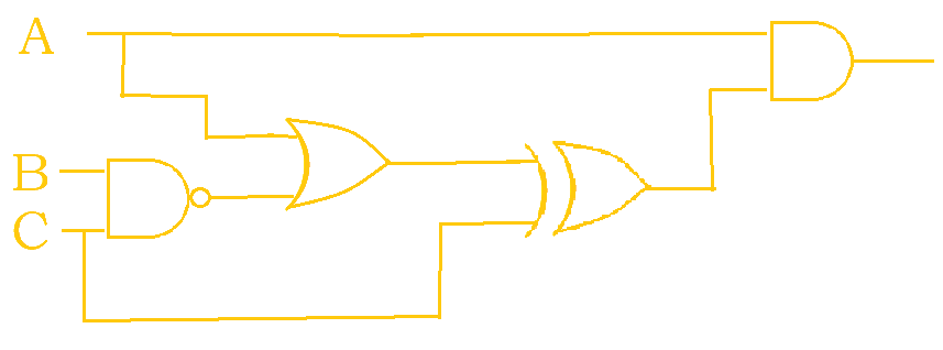
This circuit will first be written as a boolean expression for better ease of solving.
$\overline{BC}$$A + \overline{BC}$$(A + \overline{BC}) \oplus C$$A \bullet ((A + \overline{BC}) \oplus C)$
Broken up, this would become $A \bullet ((A + \overline{B} + \overline{C}) \oplus C)$. Now, a truth table can
be made to get the solution. Note that the 4th and 5th columns are labeled with a q and r just to make avoid
having to write the entire expression over again in the next column.
| A | B | C | $A + \overline{B} + \overline{C}$ |
$q \oplus C$ |
$A \bullet r$ |
|---|---|---|---|---|---|
| q | r | ||||
$0$ |
$0$ |
$0$ |
$1$ |
$1$ |
$0$ |
$1$ |
$0$ |
$0$ |
$1$ |
$1$ |
$1$ |
$0$ |
$1$ |
$0$ |
$0$ |
$0$ |
$0$ |
$0$ |
$0$ |
$1$ |
$0$ |
$1$ |
$0$ |
$1$ |
$1$ |
$0$ |
$1$ |
$1$ |
$1$ |
$1$ |
$0$ |
$1$ |
$1$ |
$0$ |
$0$ |
$0$ |
$1$ |
$1$ |
$0$ |
$1$ |
$0$ |
$1$ |
$1$ |
$1$ |
$0$ |
$0$ |
$0$ |
So, there are 2 ordered 3-tuples that make the circuit true: (1, 0, 0) and (1, 1, 0).
Author: Kelly Hong